Applied Particle Physics, Hydrogen Energy and Renewable Power Research

A 4-digit target RPM as well as a 4-digit measured RPM (see Hall Effect sensor below) are to be displayed on Dashboard.
Compare measured RPM to target RPM and electronically reduce/eliminate differences to align them.
If measured RPM is too high then less power/current/voltage delivered to DC motor.
If measured RPM is too low then more power/current/voltage delivered to DC motor.
This regulation achieved best by Proportional-Integral-Differential (PID) Control (see below)
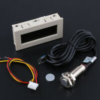
The measured RPM can be delivered by a magnetic Hall Effect sensor shown in photo below.

PID Control is practical implementation for generic feedback loop control problems. P=Proportional deploys absolute difference between measured RPM and target RPM. I=Integral deploys cumulative sum of past differences. D=Differential deploys rate of change of differences. In general, all three deliver best control to force differences to zero achieving constant speed regardless of the cause of the deviations from constant speed.
In addition to the Arduino approach is the Beagle Board Blue. This board contains motor drivers and is intended for robotics apps. Not sure what are the differences between the Arduino and the Beagle Board, but both need to be tried to just learn about both.
Either way, the Dashboard seeks to use something for PID Control and calculating the arbitary functions of the sensor readings for display to the Operator, and Arduino or Beagle Board appear to be the obvious initial choices.